What is Mozart?
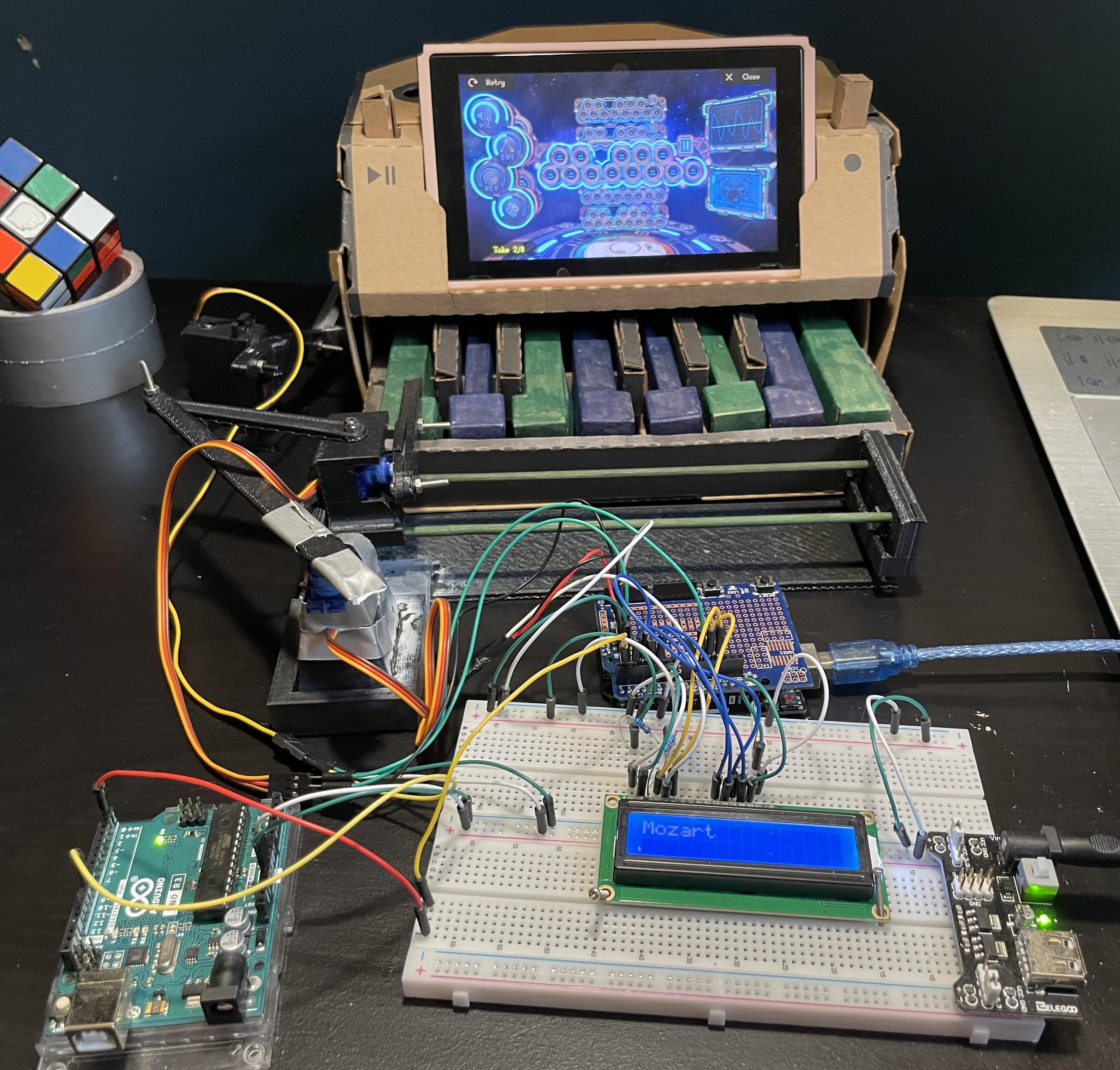
Mozart is a piano playing robot I made over the summer of 2024. It uses three servos to play songs on a Nintendo Labo piano. Additionally, via a USB Cable, it can listen to instructions from my computer to play preset songs and sight-read!
Why Mozart?
As I was preparing to enter my freshmen year at UIUC, I was looking around my house for projects to work on. For a while, I was stumped, unable to find anything interesting enough to work on. Then, as I was going to bed one night, it hit me. Literally. My Nintendo Labo toys fell down from my shelf onto my bed as I nudged them slightly while getting into bed.
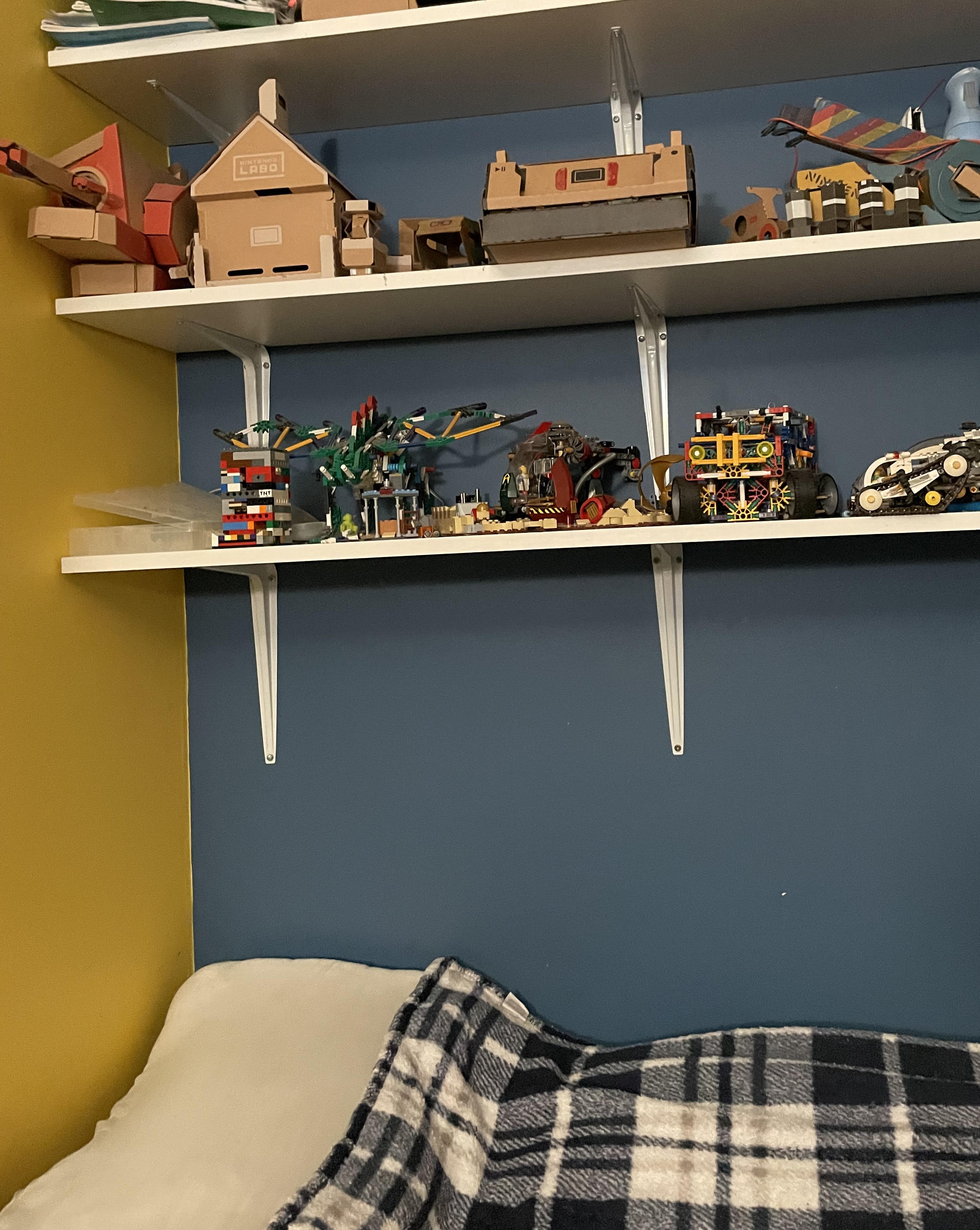
I’ve always loved those YouTube videos where programmers teach AI’s how to play games. So I thought, why not make a robot that can play with these toys. Most of the toys are far too complex to automate, such as the house, where different blocks needed to be moved around different locations of the toys with extremely complex and precise movement that would be hard to replicate consistently with a robot. Finally, after looking at each toy, I decided on the piano because it could play simple songs with the press of a few keys.
How Mozart?
Defining Mozart’s Goals
First, I defined my goals for the project. Mozart will be able to …
- Play any note on the song, including different octaves
- Communicate with my computer to play simple songs
- Sight read songs from sheet music
Research Other Robot Pianos
Next, I did some research and found other robot pianos for inspiration. Below are the projects that had the most impact on Mozart’s design.
-
- Wooden robot frame with tube slider
- Uses two servos to (1) switch which key was hovered over and (2) press a key down.
- Two linkages were connected from servo 1 to the carriage servo 2 sat in, in order to convert the rotational movement of the servo 1 into a linear movement of the carriage with servo 2.
Prima - a Robot That Plays Piano
- Modeled and 3d printed robot frame. Used smaller thin metal sliders for the carriage to sit on.
- Same linkage system as above.
-
- Uses a Raspberry Pi Camera and the Audiveris software to sight-read sheet music.
- Play keys using many solenoids
There were many other piano playing robots out there that used human liked hands and many servos like the Piano-Playing Robot above. However, I only had three servos and no solenoids, so I decided to mimic the key playing capabilities of the first two links above. While this two servo system could not play two notes at once, they could still play simple songs, which was enough for my goals. Additionally, I loved the way the third robot sight-read music using Audiveris since creating my own OMR (optical music recognition) system was out of the scope of this project due to the amount of time it would take to create a reliable system.
Thus, I decided my actuators would be…
- 3 Servos
- The Octave Servo to switch octaves using the slider on the side of the piano
- The Finger Servo to press keys down
- The Control Servo move the above Finger Servo to every note on the piano
In order to control these servos, I decided to use an Arduino UNO since I had many lying around. Additionally, I also wanted to use an LCD screen to display data to help me debug the program. I initially thought there weren’t enough PWM pins on the Arduino UNO, and thus ended up using two connected Arduino to control the servos and the display even though I only needed one.
Designing Mozart
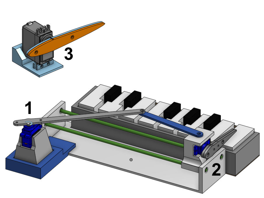
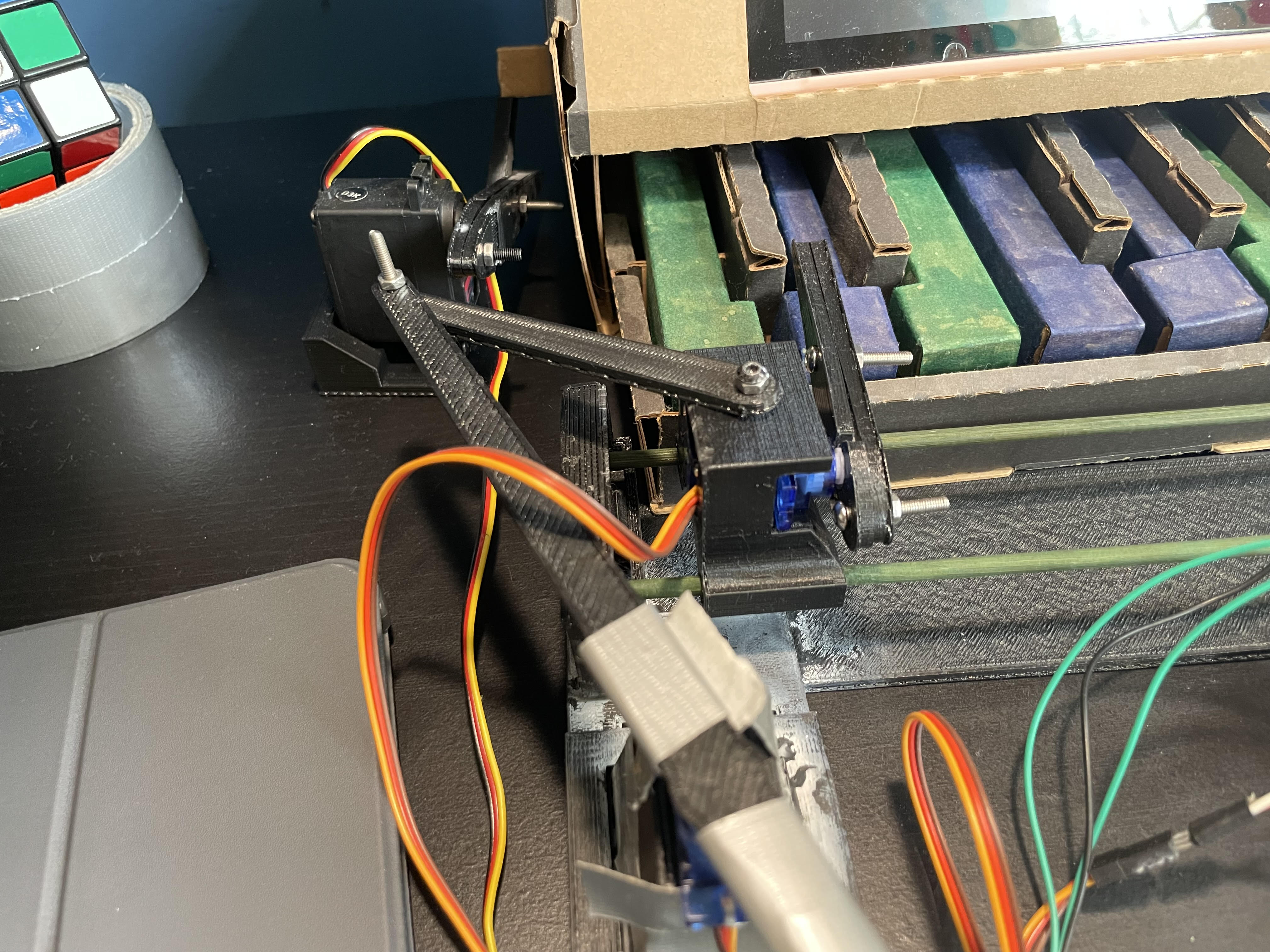
Alone each servo does absolutely nothing. In order to make the servos useful, I designed a chassis consisting of three parts. The first part is the control tower holding the Control Servo, which is connected to the Finger Servos via two linkages. Like the Robotic Piano Player, this converts the rotational movement of the Control Servo into linear movement of the Finger Servo. Speaking of the Finger Servo, the second part consists of a carriage holding the Finger Servo (where the linkages connect the Servo to the carriage) and a slider which the carriage moves across. Lastly, the third part is simply the Octave Servo moving the slider up and down to change the current octave.
Below is the CAD Diagram.
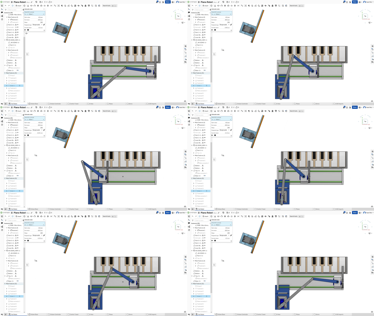
And here is Mozart’s carriage moving across the slider.
Design Philosophy
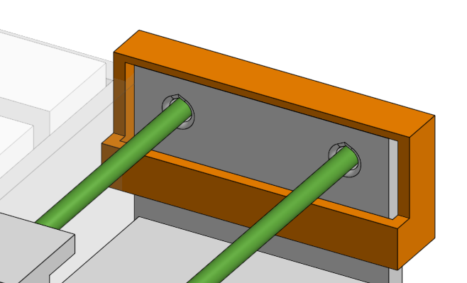
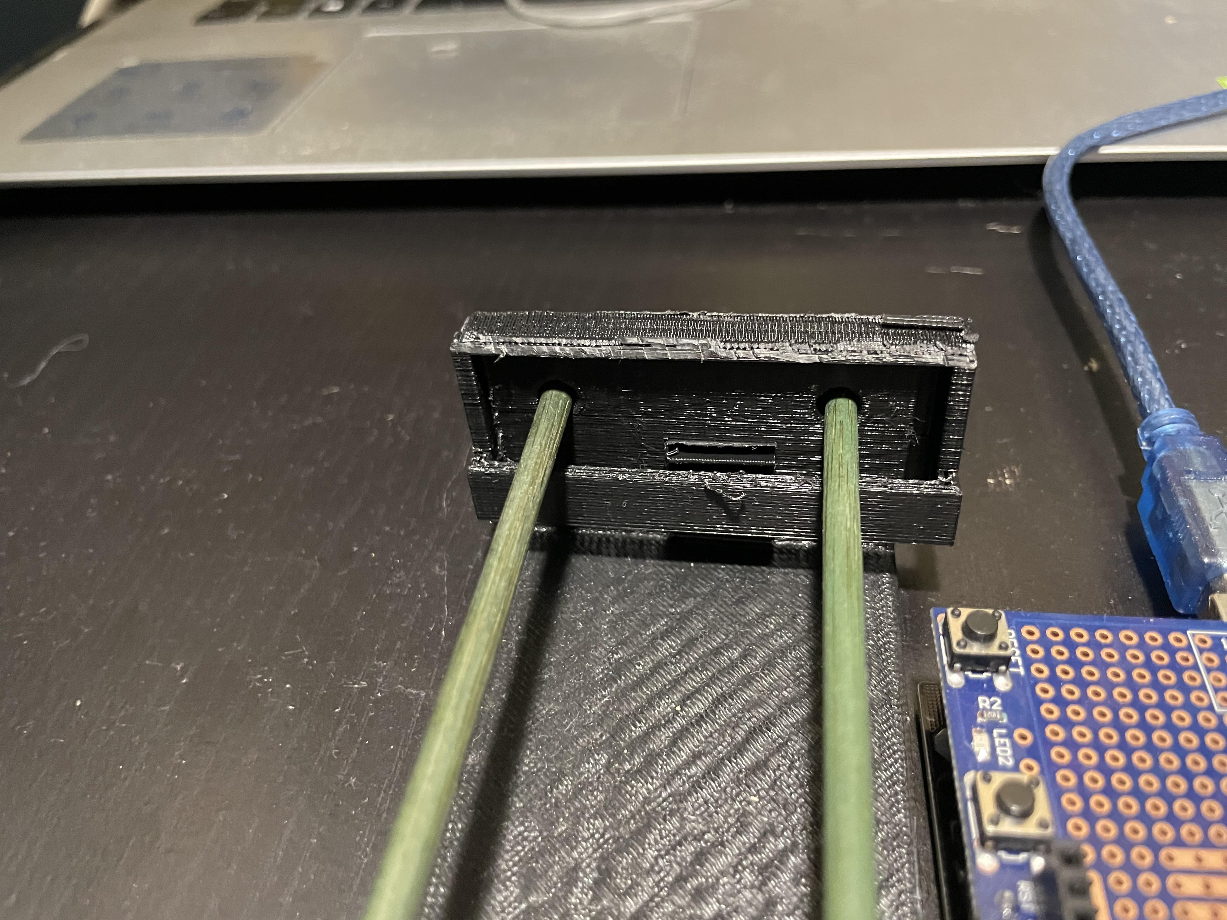
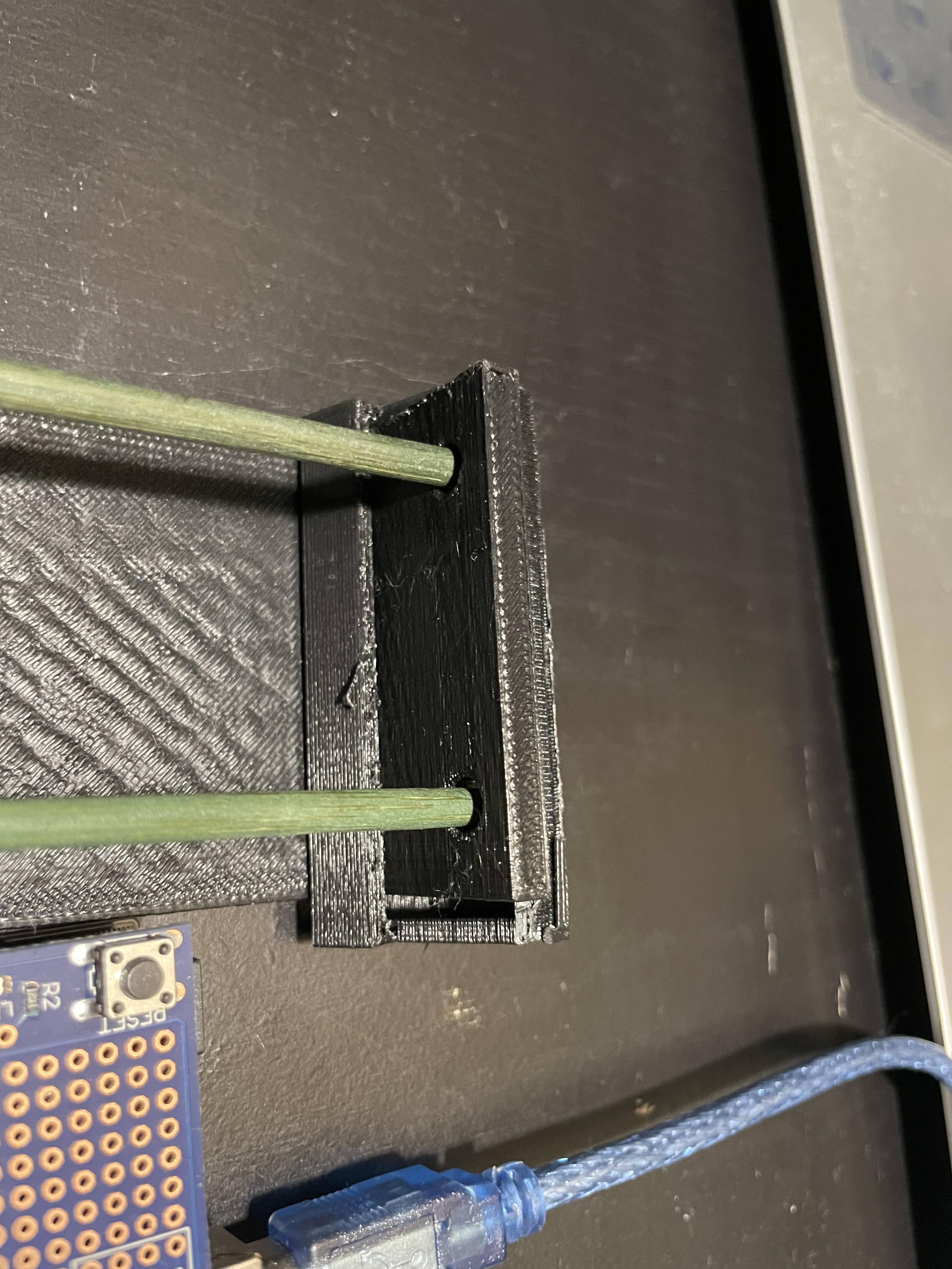
While designing Mozart, I prioritized repairability so that if something breaks, like one of the wooden slider bars for example, I can easily replace them with new ones without reprinting the chassis and/or removing lots of glue. I did this using caps that weren’t part of the main chassis. This way, the cap would hold the slider in place during normal use, but if the slider broke, the cap could be nudged off and the slider could be replaced.
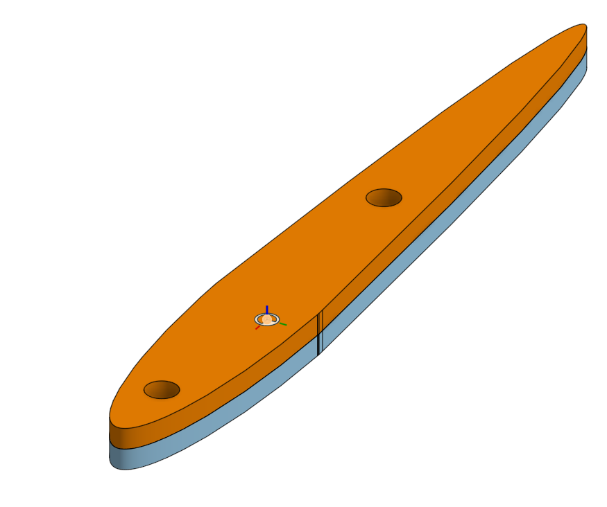
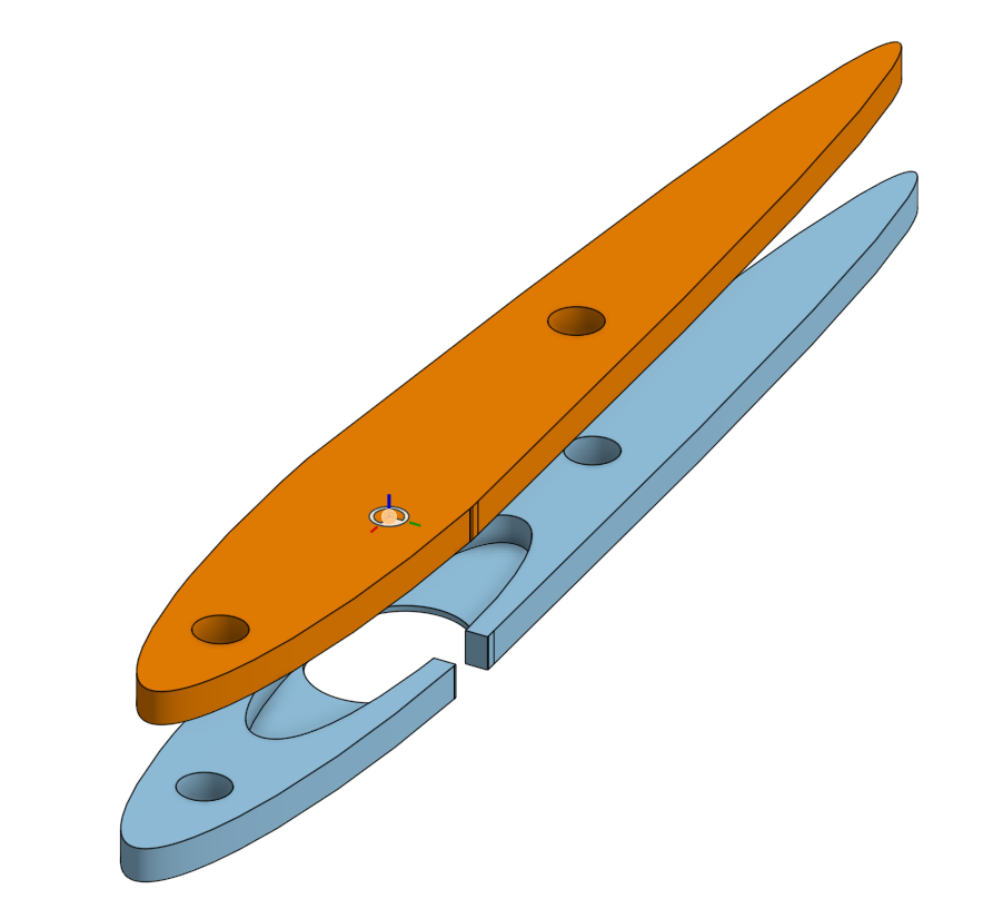
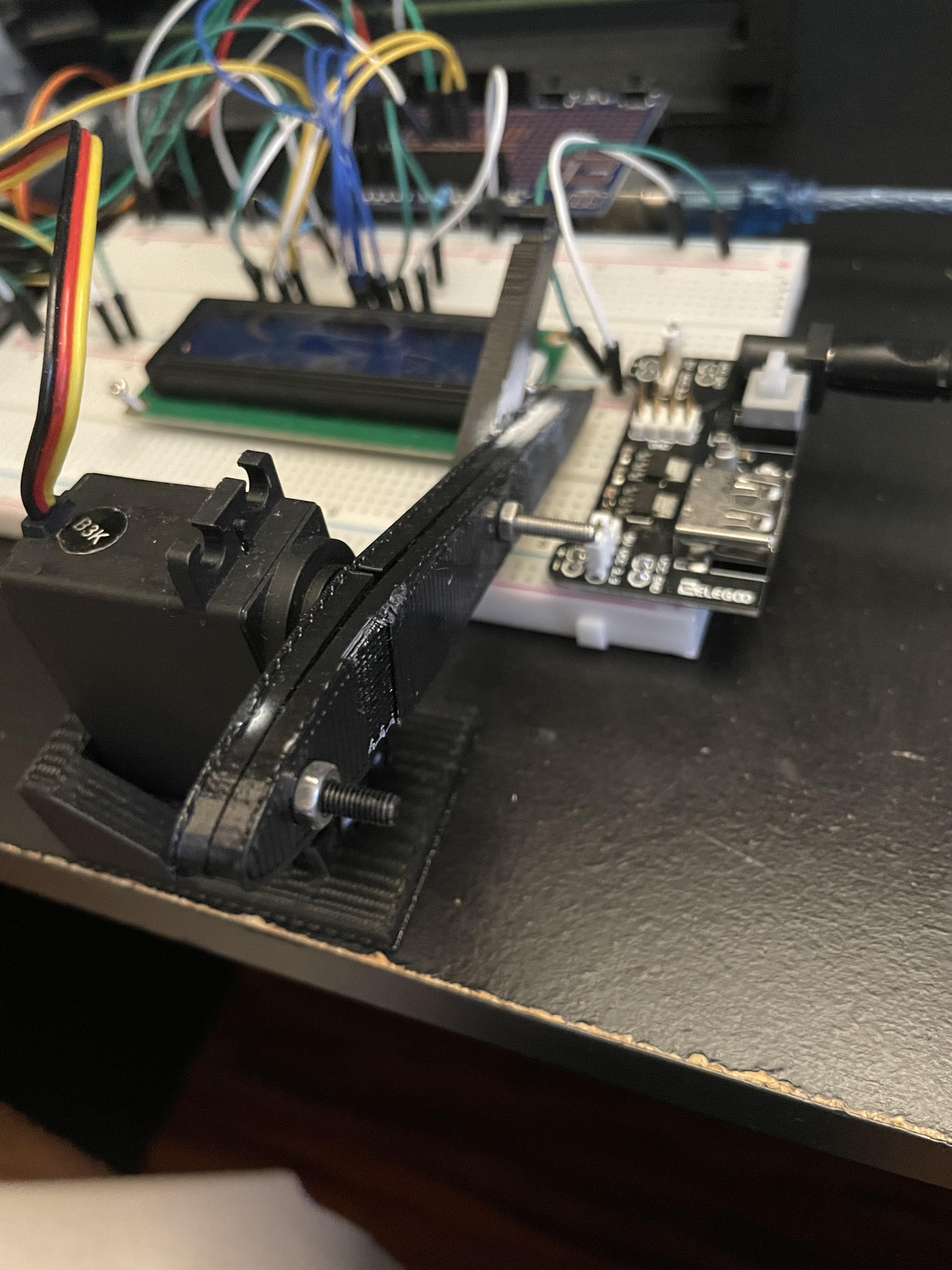
Additionally, I followed the same principle for the arms of the servos. For the control servo I simply attached the arm on with duct tape. However, this was annoying because the tape would lose strength over time. So for the other servos, I created a 3 part arm system that would grab onto the small built in servo arm and match its angle. This way, I could easily tighten or loosen the arms without using more duct tape.
Design Problems
While designing Mozart I encountered many issues. Here are some of the ones I learned the most from.
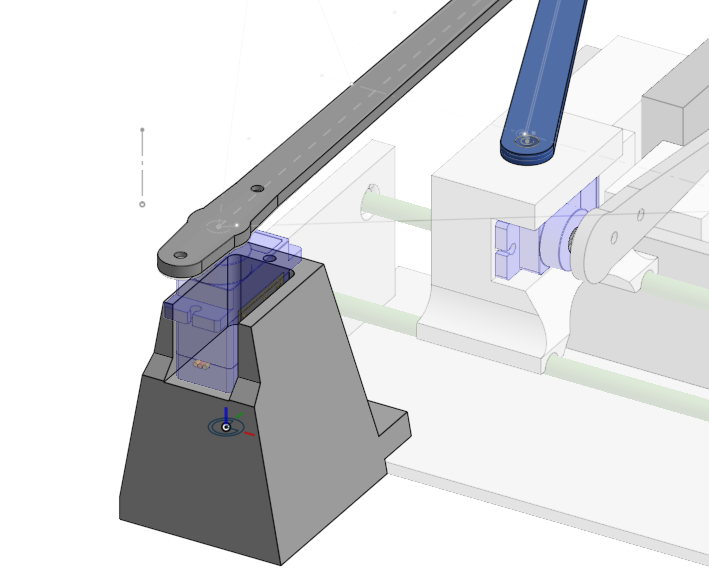
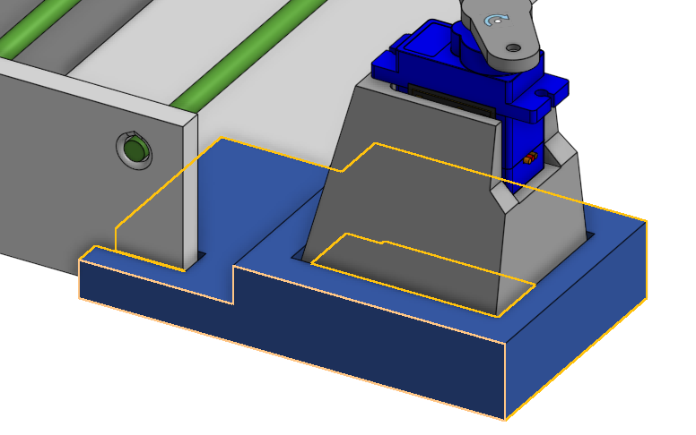
- Initially, I had the Control Servo right against the slider. However, after testing this, I realized that the carriage wouldn’t budge as the Control Servo spun, instead the carriage just rotated in place. To fix this, I looked back at my research and noticed both the Robotic Piano Player and Prima placed the Control Servo slightly behind the slider. I tried this out by holding the servo in place with my hand and rotating it, and the extra space worked! Thus, I added a small spacer between the Control Servo and the slider, resolving the issue. From this I learned that I should test mechanisms in real life more before 3D printing it completely to ensure they work properly and thus save plastic and time. (Time especially because my printer is very slow)
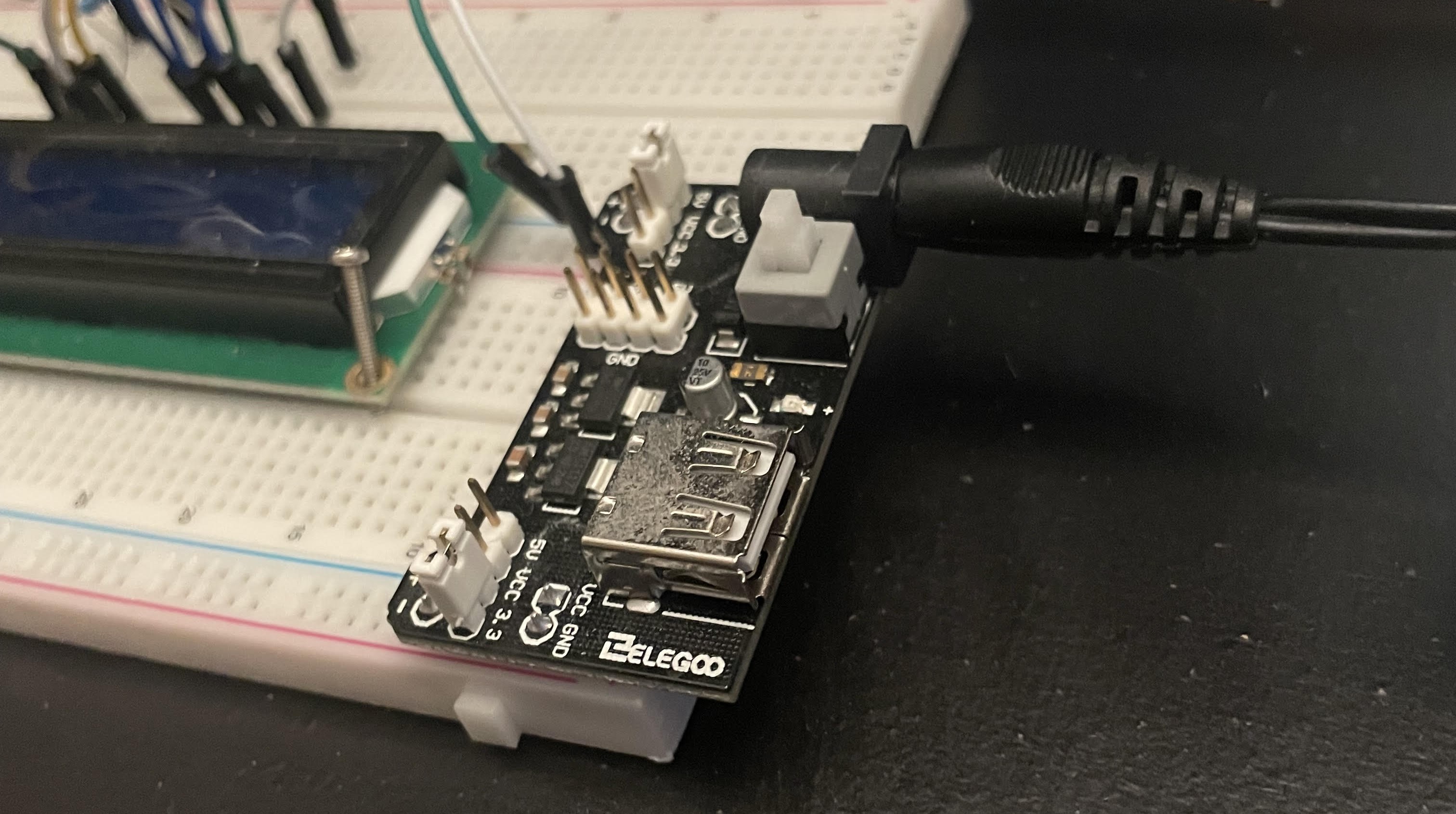
The carriage couldn’t make small adjustments easily when the control servo moved slightly. After some testing, I concluded that this was because the torque of the control servo wasn’t strong enough to overcome the static friction between the rails and the carriage. The rails were just random wooden sticks I found lying around because I lacked any alternative pieces. I resolved this by adding an external power supply, providing the servos with much more current and thus the torque required to overcome the friction.
Initially, I wanted to join the linkages together using bent paper clips. However, after trying this, I immediately realized that the paper clips could not hold the weight of the linkages up. Thus, I looked back at my research and found that the Robotic Piano Player used screws to join linkages together. Copying this, I was easily able to connect the carriage to the control servo using screws and linkages!
Wiring Mozart
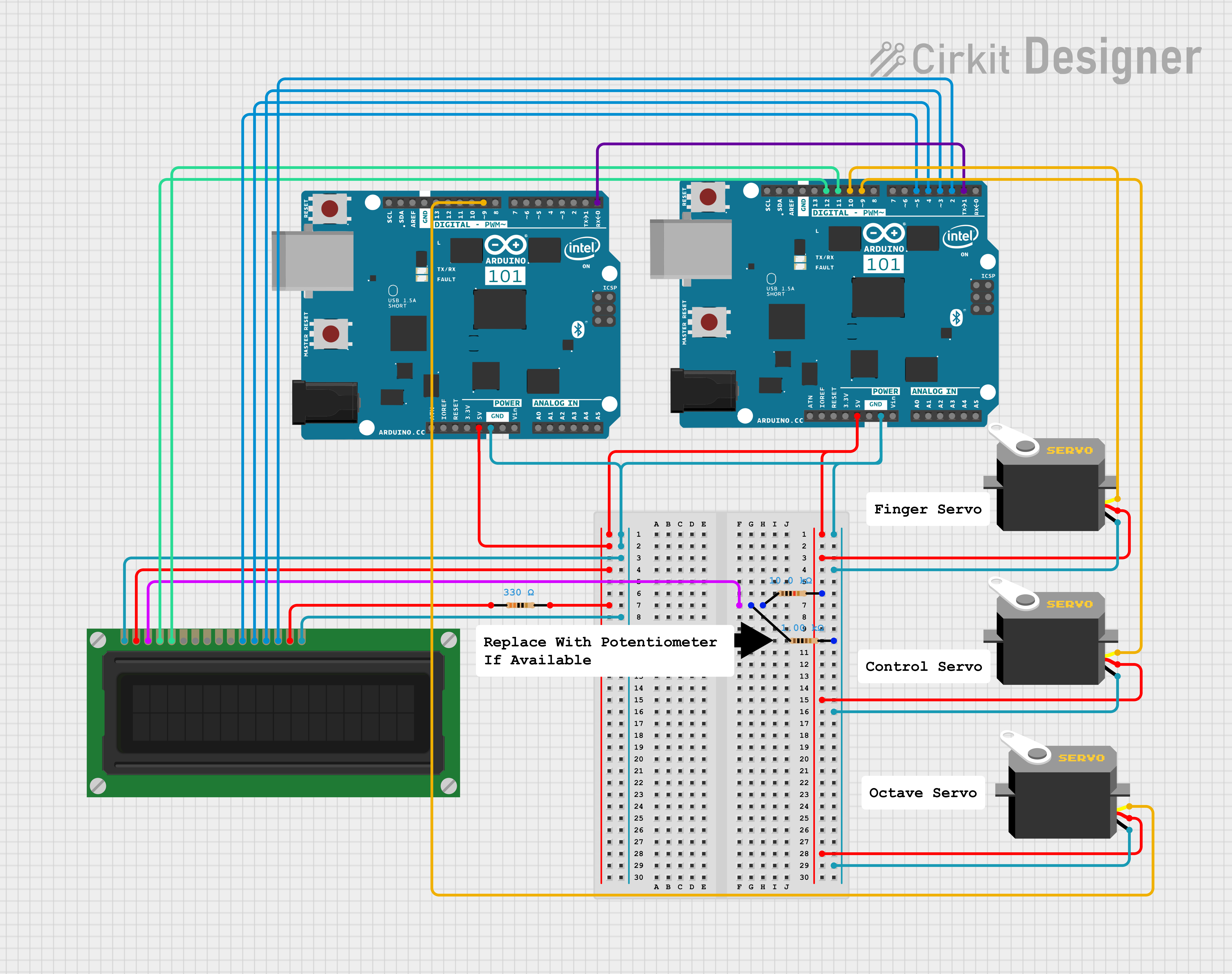
While Mozart was being brought to life mechanically, I also fully wired it up to the Arduino UNO in order to test my mechanisms. I created the following wire diagram afterword to show my work. One thing I learned from this process is that I should’ve done my wire diagram before I began wiring since I would’ve known I only need one Arduino for the project. Instead, I connected the Arduino to another Arduino via the RX and TX pins, which I hadn’t realized was possible. Funnily enough, this small mistake of missing a PWM pin actually taught me a lesson about UART communications. Additionally, when wiring the LCD, I realized I had no potentiometer to adjust the contrast, so I learned how to make a makeshift one using two resistors.
Programming Mozart
Lastly, after wiring and building Mozart I had to program it. I thought this part would be easy since it was just controlling three servos, but I was wrong.
Inverse Trigonometry
First to practice my mathematics, I solved the inverse trigonometric equations for Theta (the angle of the control servo) as a function of the slider’s position. Here is the equation I solved for.
Work available here | Graph available here 
Then using that equation, I solved for the angle of the control servo for each key on the piano. This worked relatively well, but I had to do some minor tweaking to because the arm was slightly off from some keys sometimes. Overall, the inverse trigonometry was fun, but unnecessary since guess and check would have worked much faster. However, I learned a lot from this process and will definitely use it in future more complex projects where guess and check won’t work.
Here are the angles for each key on the piano.
Mozart.inocpp
Mozart App
In order to play any songs on the piano, Mozart needed instructions. So I created a simple app that would send instructions to Mozart from my computer. The app was written in Python due to is simplicity and because of the Custom Tkinter Library which let me easily create an appealing GUI. Then using MuseScore, I created sheet music for each song I wanted to play and saved them as mxl files. Finally, the app reads these mxl files and sends the instructions to Mozart.
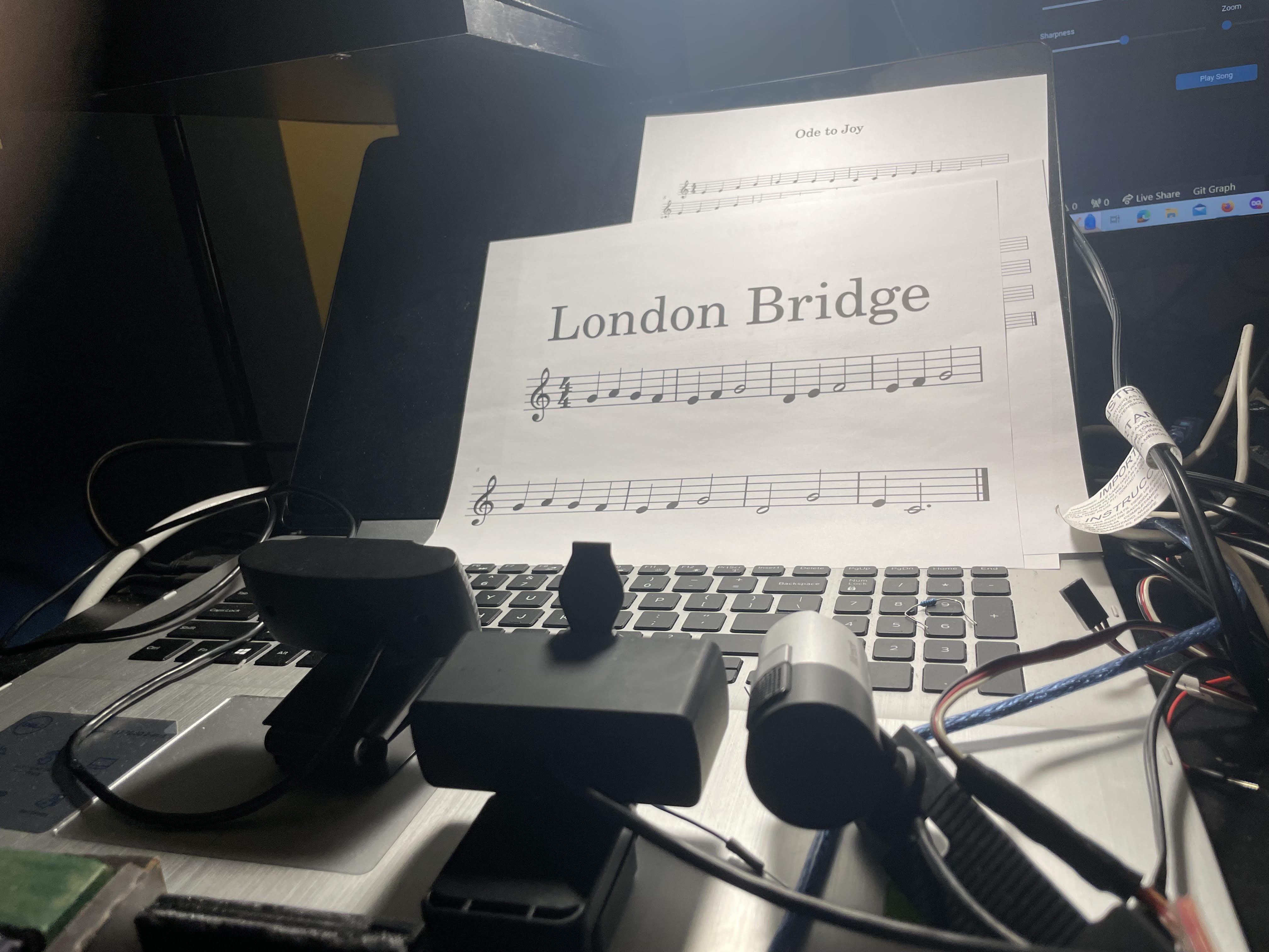
Furthermore, the app interacts with the Windows API in order to scan images from my printer. Originally, I wanted to use a camera to scan the sheet music, but after much testing I wasn’t able to get reliable results. Thus, I used my printer to scan the sheet music because its results were more consistent. After scanning the sheet music, Audiveris converts the scans into a mxl file for Mozart to play.
Programming Problems
When the Servo was given a command to move to a certain angle, it would take a different amount of time depending on the difference between the current angle and the desired angle. Initially, I was just using a constant delay after the Control Servo was given a command no matter what angle was given, but sometimes this would cause the Finger Servo to push down before the Control Servo was done moving. To fix this, I researched different delay methods and found a library called VarSpeedServo that allows you to wait until the servo is done moving before continuing, fixing the issue. Additionally, this solved the problem of the Control Servo overshooting the carriage due to the carriage gaining high velocity as the control servo accelerated it, making it hard to precisely move the carriage. Thus, by rotating slower, the carriage moves more smoothly at slower leading to more consistent results.
I send Mozart instructions 10 characters at a time. When I began testing Mozart, I noticed that I had to send a 10 character dummy instruction first before the actual song in order for Mozart to play the correct song. At the time I had no idea why it worked, but after adding sight-reading to the app, sending songs completely broke. After lots of testing, I realized the reason why sending songs wasn’t working and why I needed to send a dummy instruction: The delay after connecting to the Arduino was too short. The dummy instruction increased that delay which temporarily remedied the issue, but now I removed the dummy instruction and made the delay after connecting longer. In the future, I’ll make sure I understand why something words before just going along with it since it caused me such a headache in this project.
I spent way too much time trying to get the camera scan to work properly. After pretty much a week of testing with different cameras, different settings, and different software, nothing worked. Finally, after talking to my friends I switched to my printer scanner because it took much cleaner images that Audiveris was able to decode. Instead of trying to fix the camera, I should have started from the ground up and initially scanned online sheet music, then moved onto the printer scanner, and lastly try using a camera. This way, I wouldn’t have wasted so much time on the camera portion of Mozart.
The Control Servo wasn’t accurate enough to play accidentals. Initially, I wanted to play songs that included sharps and flats, but after playing around with Mozart, I realized the Control Servo wasn’t accurate enough to place the finger right above the small black keys. Thus, I decided to only play songs that used the white keys since they were much bigger and easier to hit.
Conclusion
Mozart can play and sight-read simple songs very consistently. In order to achieve this high accuracy, I made many speed sacrifices such as lowering the servo speed and using my slow printer scanner instead of a camera. The project has taught me a lot about inverse trigonometry, how to create linkages, and how to make a simple app that can communicate with a robot.
If I were to improve this project in the future, I would definitely look into alternative methods of sight-reading, such as perhaps creating my own OMR system that can handle less precise images from a camera. Additionally, I would create a system that relied on 13 solenoids (similar to the Piano-Playing Robot) to play each key instead of the current two servo arrangement because that would allow Mozart to play multiple notes at once, and play accidentals. Lastly, I would create an enclosed case for Mozart to make it easier to transport and store.
